Welcome to segment 1 of 4 examining the use of aerial robotic systems for contact-based UT measurements. In this segment, we examine this new pioneering aerial robotic measurement technology and how it operates. In the next segment we consider the benefits and constraints of these systems, in segment 3 “it’s all about data”, reporting, and more, and in segment 4 we review how these systems can be used in your organization and what may be in store for the future of this exciting technology.

Introduction

     For corrosion or other engineers to take Ultrasonic Thickness (UT) measurements at height they may need to utilize a lift, scaffolding, ladders, inspection trucks with elevated baskets, ropework, catwalks, cranes, rigging, or other solutions. While NDT inspection programs can dramatically increase the safety and integrity of assets, access requirements in performing these inspections in elevated areas introduce risk. Working at height is dangerous, due to the possibility of falls, as well as being time-consuming due to access set up. In certain instances, it may also require taking an asset, such as a flare stack, offline so it can be accessed to take measurement readings.

DeFelsko+Positector+Hand+Held+Electronic+Measurement+Gauge

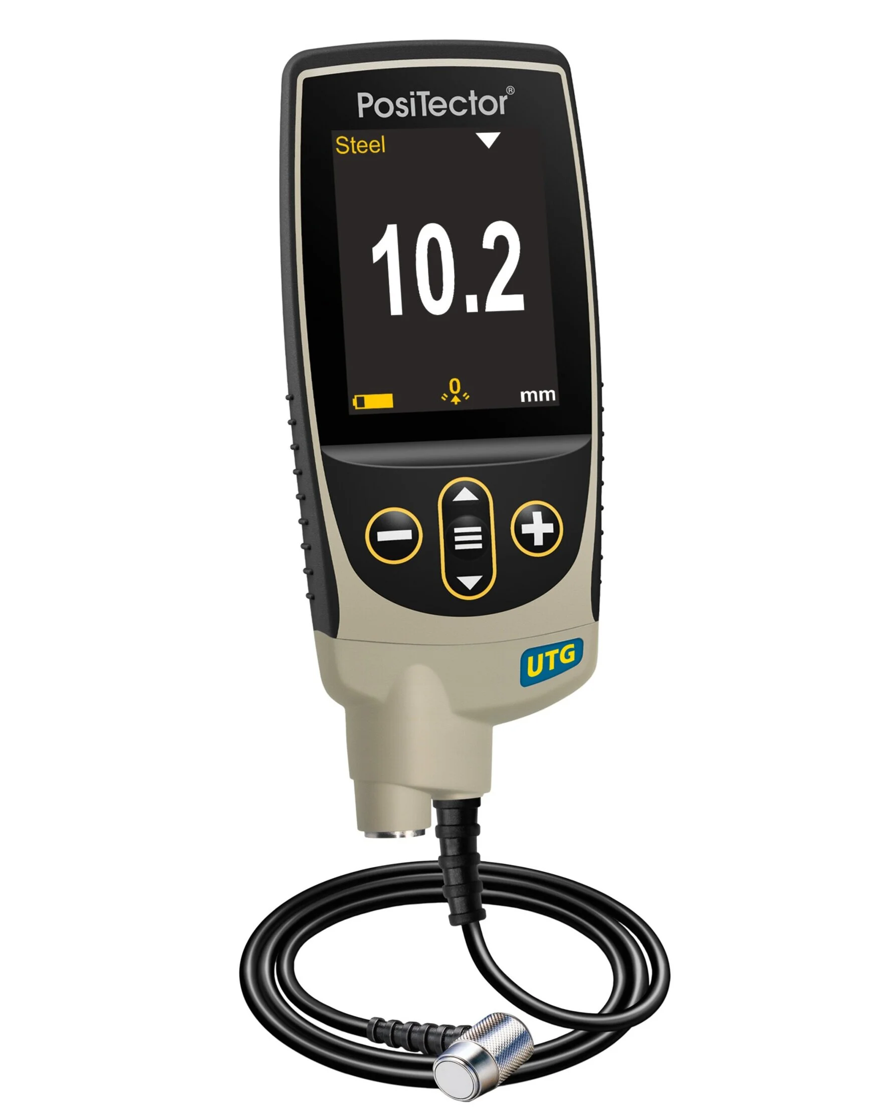
Image 1 - Representative photo of a multiple-echo ultrasonic wall thickness measurement device, a DeFelsko PosiTector UTG-M gage with single-element 5 MHz contact transducer[1]

Current Measurement Collection Methodology

     Electronic UT measurement devices have a long history of measuring ferrous substrates. According to a major manufacturer of these devices; “Most coatings on steel and iron are measured this way[2]” providing thickness readings frequently shown on a liquid crystal display (LCD) with a measurement tolerance of ±1% [3].

A typical “Manual” measurement system/process works as follows.

  • An individual or corrosion engineer is trained and often certified, for “working at height”.

  • Access may include finding a ladder, erecting scaffolding, securing the use of a lift or crane, etc. Access could also utilize components built into the structure such as ladders, handholds, etc.

  • The worker then obtains access to the area of a structure wearing the appropriate safety equipment including fall protection and restraints and carrying a handheld electronic UT measurement device. Often this requires at least two people, as climbers need to use a “buddy system”.

  • Once the worker is in the correct location, they utilize the handheld electronic UT measurement device to touch the probe tip to the surface and take measurements.

  • The worker then safely “moves” to the next location(s) and repeats the process.

  • The worker then safely “comes down” from the location(s) at height and creates a report of their findings.

Worker at elevation taking manual NDT measurements

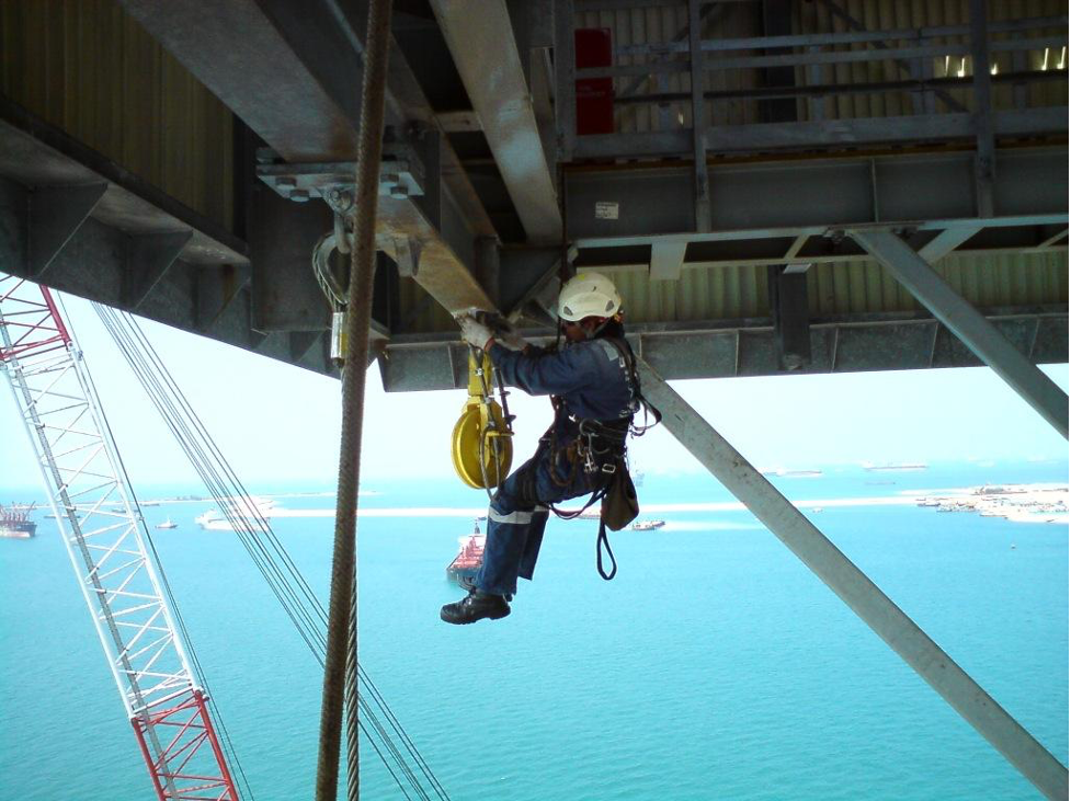
Image 2 - Current state of the art for obtaining Contact Based NDT Measurements [4]

New “Aerial Robotic” Measurement Collection Methodology

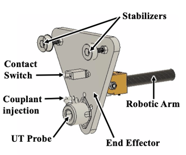
Apellix has developed the Opus X4 UT computer-controlled heavy-lift multi-rotor drone outfitted with various sensors and functions to allow precisely controlled flight close to structures. Manual control of such systems is unable to accomplish the precise flying and maneuvers required; thus software-controlled flight is crucial. The Apellix aerial robotic systems utilize existing electronics and digital probes to perform UT measurements with the device onboard the aircraft streaming data (not just what would be displayed on the LED view screen) to the onboard computer. This innovation was named a 2017 Corrosion Innovation of the year by the National Association of Corrosion Engineers (NACE) [5].

Apellix Opus X8 measuring UT on an in service storage tank and flare stack

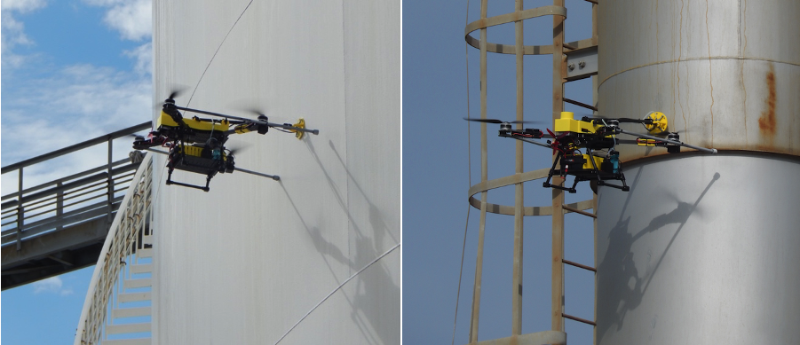
Image 3 - Apellix Opus X4 UT Measurement System taking NDT (UT) measurements on an in-service aboveground storage tank and an in-service active Flare Stack [6]

The Apellix Opus X4 UT aerial robotics system works as follows.

  • The tethered (for data and power) or untethered (battery power and wireless data) aerial robotic system is located close to the structure where UT measurements are to be taken.

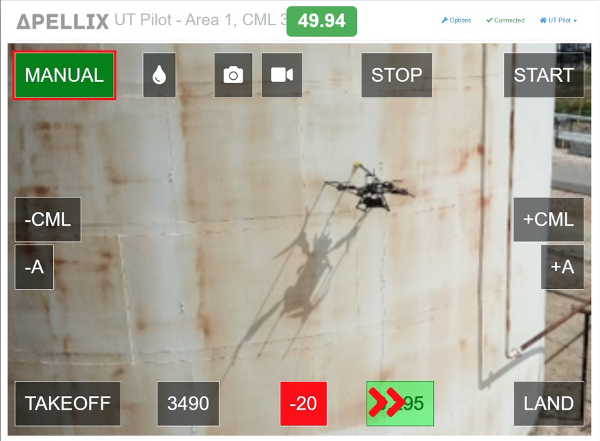
  • The corrosion engineer using a computer tablet (such as an iPad) opens the software interface to begin the test and enters the job information (operator, job name, upper and lower limits for measurements, etc.).

  • The pilot engages the aerial robotic systems software and the system takes off vertically to approximately 2 meters in height, hovers, and completes self-checks.

  • The pilot then uses a standard handheld radio frequency transmitter [7] to manually fly the system close to where the UT measurement is to be taken. i.e. the “gate” or “window”.

  • Once the aerial robotic system is within the “gate” (i.e. ~2 meters from the target part of the structure) the pilot chooses “Start” on the software interface.

  • The system then operates under full computer control (no manual input). It flys in (whilst dispensing couplant gel onto the probe), touches the surface, and takes a UT measurement reading, typically taking 1 to 4 seconds, with multiple data points. The aircraft then backs away, the pilot repositions the system at the next location, and repeats the process for additional measurements at different corrosion monitoring locations (CML) or areas/zones

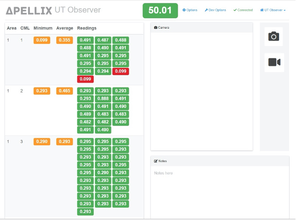
  • The corrosion engineer, ships surveyor, etc. sees the data on their computer tablet in real-time.

After landing, the operator has the option to download the full data record which includes all the UT readings, HD video, and additional information such as locational coordinate data, weather, and environmental data, etc. The data is also made available in the secure Apellix Flight logs data repository accessible via the Internet. The Apellix Opus X4 UT system is agile and mobile enabling it to take a lot of readings in a short amount of time. Depending on the condition and geometric complexity of the asset being measured as well as environmental and weather conditions, the system can take measurements at up to a few hundred contact locations per hour.

Opus X4 UT Pilot view on portable computer/tablet

Image 4 - Opus X4 UT Pilot User Interface View [8\

Opus X4 UT Corrosion Engineer view on portable computer/tablet

Image 5 - Opus X4 UT Corrosion Engineer User Interface View [9]

Opus X4 UT Pilot view including camera mounted on the drone on portable computer/tablet

Image 6 - Opus X4 UT Onboard Aircraft View [10]

Aerial Robotic System UT Technology

UT measurements require the application of a couplant gel to the measurement probe tip prior to taking a reading [11]. Thus, the end effector at the terminus of the robotic arm has a mechanism to dispense the couplant prior to each contact with a structure. There is a reservoir of couplant gel on the aircraft with a pump and motor connected to a small diameter tube that runs the length of the robotic arm and attaches to the end effector. The onboard computer, via the embedded software programming, signals the pump to push the couplant to the couplant injection point at a short time interval prior to making contact with a structure to take a UT measurement.

Robotic hand aka End Effector at the end of the robotic arm

Image 6 - UT Measurement Robotic End Effector [12]

Onboard the aircraft is also the Type 2 handheld electronic UT Measurement Device. Currently a DeFelsko UTG M gauge with a single element 5 MHz contact transducer [13] capable of taking echo to echo ultrasonic thickness measurements. The DeFelsko device is plugged into the on-board computer for power and data transfer. The full data record is transmitted during its use, not just what is set to display on the device's LED screen. The system uses a Wi-Fi router to connect with the on-board computer which, amongst other things, allows the aircraft to communicate with the pilot and the corrosion engineer on the ground, enabling it to display data in real-time. The aircraft also has an on-board HD camera and may include a “gas sniffer” which records concentrations of various gas levels and notifies the system operators if certain thresholds of gas are detected. All the data from the onboard computer is saved to a memory card/USB flash drive. The data is made available in the internet accessible secure Apellix Flight log reporting and data repository with the ability to create charts, graphs, download data, etc.

The Opus X4 UT systems are complex robotic systems designed to fly in locations standard drones are not designed for.

Onboard sensor data custom circuit cards

Image 7 – Apellix Custom onboard Printed Circuit Board [14]

Conclusion

While industrial UT inspections are necessary and critical, they can be expensive and dangerous. The Apellix Opus X4 aerial robotic inspection systems and automation help organizations improve safety and reduce costs by performing UT measurement jobs safer, better, and faster than completing the same tasks manually. With its unique ability to gather data, the system can allow your organization to capitalize and extrapolate on the data and information gathered providing users with a scenario wherein 2 + 2 equals more than four.

Join us next month for segment 2 where we examine the benefits and constraints of these systems, when it is the correct tool from your toolset to use, what type of performance to expect, and what use cases provide the most value creation. Then in segment 3, we discuss the data, and finally, in segment 4 we look at how these systems can be used in your organization and what the future may be for this exciting technology.


[1] Image courtesy of DeFelsko Corporation

[2]Website for DeFelsko Corporation - Retrieved 2 October 2020 https://www.defelsko.com/resources/measurement-of-effects-of-erosion-and-corrosion

[3] Ibid

[4] Public Domain Image from Wikipedia

[5] Materials Performance Announces Winners of the 2017 Corrosion Innovation of the Year Awards http://mp-innovation-awards.webflow.io/2017-winners

[6] Image courtesy of Apellix, Working Drones Inc.

[7] The radio transmitter is the standard operations control for the aircraft. Its sole use, in this case, is for positioning the aircraft close to the area where the DFT measurements are to be taken. It is also on standby in case manual operational flight controls are needed, for example in case of a failure of the software flight operations.

[8] Image courtesy of Apellix, Working Drones Inc.

[9] Ibid

[10] Ibid

[11] Wikipedia - Retrieved 12 Sept 2019 https://en.wikipedia.org/wiki/Ultrasonic_thickness_measurement

[12] Drawing courtesy of Apellix, Working Drones Inc.

[13] For more details visit the DeFelsko website https://www.defelsko.com/positector-utg

[14] Image courtesy of Apellix, Working Drones Inc.