```[_{{{CITATION{{{_1{Promotional pop up frequency - Squarespace Forum](https://forum.squarespace.com/topic/158504-promotional-pop-up-frequency/)

Welcome to segment 3 on collecting, storing, reporting, and management of UT Measurement Data gathered from aerial robotic systems. The Apellix Opus X4 UT aerial robotic system can be called a “flying computer” and as such it is a data-gathering machine collecting a large volume of data. The next and final segment will focus on how to utilize UT aerial robotic measurement systems in your organization. It will review the value creation these systems unlock, how they can benefit your company and what may be in store for the future of this exciting technology.

Introduction

     Aerial robotic UT inspections are forecast to grow exponentially in 2021 and beyond, as asset owners and service providers realize their economic value creation, increased data collection, and safety contributions. Robotic equipment such as the Apellix Opus X4 UT system, when properly selected and utilized, positively impacts safety, time, analytics, access, and cost. All while gathering copious quantities of data.

Opus X4 NDT Measurements at Height

     Data is essential for decision making and data that can be turned into actionable information is critical.  Thus, nondestructive testing (NDT) systems such as the Apellix Opus X4 UT aerial robotic systems are force multipliers for inspecting, testing, and evaluating industrial assets for their safety, operational effectiveness, and expected useful life.  UT measurements are part of NDT inspection regimes that fall under the larger category of non-destructive evaluation (NDE). NDE includes visual inspection information as well as other data collection and is undergoing somewhat of a reminisce as data once gathered as part of an NDE regime can be analyzed using machine learning (ML), artificial intelligence (AI), Internet of things (IoT), big data, etc. This is what is being called NDE 4.0. The collected data and information can help expand knowledge by generating insights and understandings that turn data gathered from industrial inspections into actionable information to enhance and extend knowledge-based and information-driven decision-making.

Apellix Opus X8 measuring UT on an in service storage tank and flare stack

Apellix Opus X4 UT Measurement System taking NDT (UT) measurements on an in-service aboveground storage tank and an in-service active Flare Stack [1]

     The Apellix Opus X4 UT systems collect data on a scale and scope heretofore unimaginable feeding the hungry NDE 4.0 paradigm for analytics and other computational and informational purposes. Improving analytics allows organizations to create a digital alignment to physical space and processes. The Apellix industrial inspection systems capture information in real-time and accelerate the process of conducting an analysis. For progressive companies, lowering operating costs and gaining additional insight into their assets, NDE 4.0 is the way to make the data part of a completely new business model and a part of Industry 4.0.

Real-World Example

     In September 2020 the Apellix Opus X4 UT system was used to gather UT wall thickness and visual data on an in-service flare stack at an oil & gas company gas separation facility on the Alabama coast. The stack had 20-foot flames shooting out of the top of the flare while the team was safely on the ground operating the system, further highlighting the value proposition of this technology.

     The Apellix Opus X4 UT was equipped with an onboard NDT measurement gauge from DeFelsko. The Positector 6000 UTG C electronic measurement device had a single element 5MHz contact transducer and an onboard reservoir of Sonotech Ultragel couplant. The system was operated by a FAA Section 107 licensed pilot[1] under the direction of a corrosion engineer from an NDT engineering company. The system operated as a data collection vehicle only.  Apellix does not provide structural engineering support or advice.

     The NDT engineering company provided guidance as to the areas of concern where UT measurements were required. These Condition Monitoring Locations (CMLs) were pointed out to the aircraft system pilot by the NDT Engineering company personnel. Representatives of the asset owner were on site during the flights. The job was completed without tethered ground power to the aircraft. The total time from initial takeoff to final landing, including landings to change batteries, was under 90 minutes. Weather on the date of testing was partly cloudy with winds ranging from 5-15mph, generally from the ENE. The ambient temperature ranged from 80-90F (26-32oC) over the course of the morning.

3 Picture1a.jpg

An example of the pilot/system operator and the observer (frequently the corrosion engineer or NDT technician) screens that are streamed live to their computer tablets [2].

     A total of 104 CML were successfully sampled from 112 attempts. In 8 of the 112 instances no valid data was obtained, typically because of a wind gust or other disruption to the flight. In almost all the successful locations, multiple measurements were obtained. From the total of 535 measurements at 104 locations, the minimum (lowest) recorded wall thickness measurement is reported for the individual location. Data is stored in the onboard computer and relayed in real-time to the computer tablet of the engineers on the ground. A separate simplified data stream is presented to the aircraft pilot. Location data is tracked using cameras located on the ground and on the aircraft. During the flight, an HD video is also recorded for post-flight analysis and use.

An example of UT reading locations on a section and min thickness UT measurements on an in-service flare stack [3].

     The flare is approximately 68 feet tall with a catwalk at approximately 55 feet. Sections from approximately 8 feet above the ground to approximately 4 feet below the catwalk were tested. A ladder obstructed measurement on the southwest and west side of the stack. A vertical pipe rack obstructed measurement on the northeast corner of the stack. During the course of the flights, the engineers had access to the Apellix user interface that streamed the UT reading measurements in real-time. Within one week post-flight, Apellix delivered a report containing all data supplemented with photo documentation and location data.

3 Picture3.png

An Interoperability example of UT measurement readings data from the Apellix Aircraft API or optionally the Apellix cloud Flightlogs system
(note UT reading values are illustrative) [4]. 

     The UT reading measurement data was made available as an Excel spreadsheet and a comma-separated value (CSV) file and included UT Area Number, UT Condition Monitoring Location (CML) Number, the UT Thickness Measurements, and GPS Geolocation information. The GPS information at +/- 2 meters is not accurate for locational analysis. Additionally, access to the Apellix Beta Flightlogs secure data repository was made available. A video of how the Apellix Flightlogs system operates can be found at https://youtu.be/e_M3OXhbXP8

3 Picture4.png

 An example of UT measurement readings report from the Apellix Flightlogs system
(note UT reading values are illustrative) [5].

     Using an industrial aerial robotic inspection system like the Opus X4 UT has a multitude of benefits but also has limitations. As with any tool, selecting the correct tool from your toolbox is important and care should be taken to ensure you choose it and use it appropriately.

3 Picture5.png

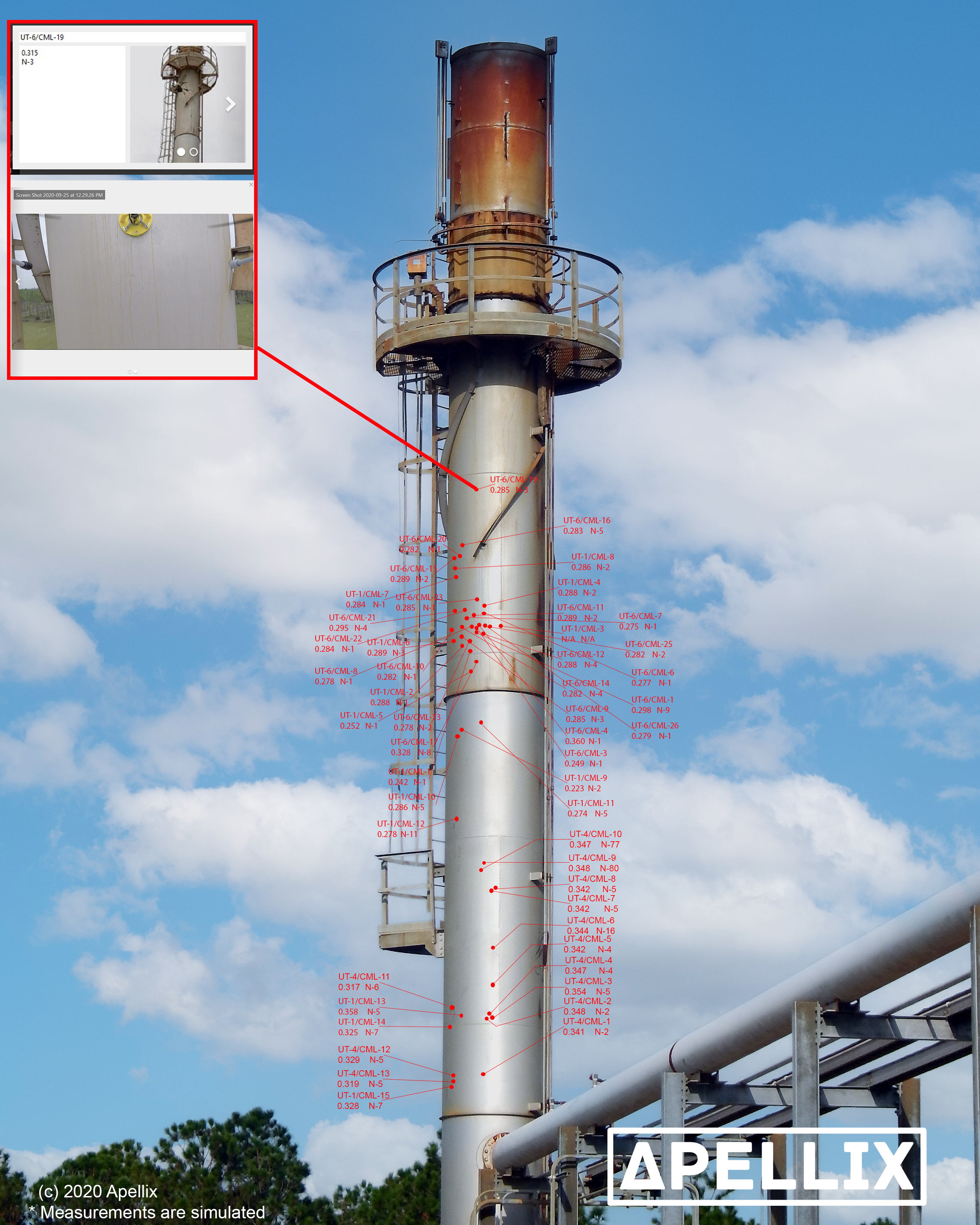
An example of flight details with UT measurement readings report from the Apellix Flightlogs system (note all numbers and values are illustrative) [6].


UT Measurement Collection

     Electronic UT measurement devices have a long history of measuring ferrous substrates. According to a major manufacturer of these devices; “Most coatings on steel and iron are measured this way [7]” providing thickness readings frequently shown on a liquid crystal display (LCD) with a measurement tolerance of ±1% [8].

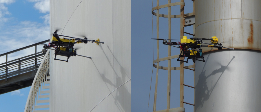
     The Apellix Opus X UT system is a new technology. Its operation is constrained by wind and rain, and the system cannot prepare the surface being tested. As an airborne device, operations are dependent on good weather and performs optimally in wind speeds less than 10 knots.  Reduced performance is observed above that level and we generally do not fly in winds above 17 knots. Oxidation or other degradation of the surface may interfere with the onboard sensor obtaining a valid reading due to the age of the stack. Thus if a conventional UT sensor with appropriate couplant is unable to obtain valid measurement readings, the Apellix system will also not be able to obtain measurement.

Standards based measurement data

     Information from robotic inspection systems including that of the Apellix Opus X series systems are typically compared to pre-specified requirements and standards. These requirements and standards determine if the item or activity is compliant with traditional nondestructive testing standards. This in turn forms the basis for inspection procedures which enable trained personnel to scientifically evaluate current status and predicted failure risk of operational and nonoperational assets. Without the addition of the Apellix Opus X this could be a dirty, dangerous and time-consuming job. For example, API 653 (and 650), EEMUA 159 (and 183), and NBIC-RCI-1 plus multiple visual inspection standards are just some of the standards UT inspectors may need to be aware of.

     As the Opus X4 UT and other robotic systems can take many more measurements in a shorter timeframe than people, especially considering access to elevated areas, there are standards under development with NACE and SSPC, ASME and others for this new technology. This should be kept in mind as organizations look towards the future with digital twins and the digitation of maintenance systems.

Additional Data

     In addition to the UT data collected during the flight of the Apellix Opus X4 UT system, high definition video was recorded, as were still photos of the UT probe tip in contact with the flare stack when the UT reading was being collected.

3 Picture6a.png
 
3 Picture6b.png

An example of flight details showing the 6th UT measurement reading (UT-6) at Condition Monitoring Location 9 (CML-9) with the lowest measurement reading 0.215 out of three readings (n=3) with photos of the Opus X4 UT making contact with the flare stack from the post-flight report (note all numbers and values are illustrative) [9].

   In addition to the snapshot photos for each measurement location from onboard the aircraft and the snapshot of the Opus X4 UT system making contact with the flare stack from the camera on the ground, a full HD video from onboard the aircraft was recorded. This video is provided to the client for their use, for example, to review it for visual areas of corrosion or to look for surface areas of concern.

     Data gathered from high definition cameras can include visual, hyperspectral, superspectral, and other imaging data. Further additional information can be collected from sensors and devices placed in physical contact with surfaces. As NDT 4.0 is data-driven, industrial inspection robotic systems are perfect for enabling it and affording its benefits. NDE 4.0 will be crucial to its success as it provides needed data allowing for machine learning, artificial intelligence implementations, and more.

     Capabilities that the Opus X4 UT system makes available for NDE 4.0 include aerographic services that utilize 3D and other computer vision, various AI, machine vision, computational geometry, simultaneous localization and mapping (SLAM), live 3D point clouds, stereoscopic real-time video photogrammetry, and other technology innovations. This would include mature and emerging technologies such as the use of Artificial Intelligence (AI), Machine Learning (ML), Machine Vision (MV), Deep Learning (DL), big and smart data processing and visualization, cloud computing, Augmented/Virtual/Mixed Reality (AR/VR/MR), blockchains, 5G, quantum computers, special data formats, and data storage and more[10]. The Apellix Opus X series of aerial robotic systems excel at gathering the data needed to unlock the potential of NDE 4.0.

     Visual inspection can also enable a look at the “air density” and detect gas leakage using optical gas imagery camera-based systems. Similar “bolt-on” technologies to robotic systems can epitomize the data collection component of NDE 4.0 thereby augmenting the UT data collected. By outfitting a drone with an array of multimodal sensory devices collecting a plethora of data and information we can enable the best success and use of NDE 4.0 as we can provide more and better data for use and analysis.

 
Conclusion

     Given the enormous potential of industrial inspection robotic systems such as the Opus X4 UT, one can easily envision a future with robotic systems having more automation, functionality, and capability. This would enable more inspections as an increased number of inspection robots are placed in service and as functionality increases.

Data from the Opus X4 UT system combined with the safety, efficiency, and effectiveness gains a more reliable inspection eco-system and can act as a force multiplier for inspecting, testing, and evaluating industrial assets. The associated data (e.g. visual) gathered while collecting UT measurement readings can generate even more knowledge, insights, and understandings. The additional data gathered from a flight can immediately translate into actionable information and enhance and extend knowledge-based information-driven decision-making.

As we move towards a more automated future with robotic inspection tools become more advanced, affordable, and utilized, we will continue to utilize automation tools that free human inspectors from the dirty, dull, and dangerous tasks of collecting inspection data. This will enable them to spend more time on the higher value components of industrial assets operation and maintenance.


The materials and the views expressed in this document are solely those of the author(s)
and are cleared for public release


References

[1] Current regulations for commercial drone operations in the US require the pilot to be certified by the US Federal Aviation Authority (FAA) with what is commonly referred to as a “part 107 license”. More information is available at the FAA website https://www.faa.gov/uas/commercial_operators/

[2]  Image Courtesy of Apellix, copyright 2020

[3]  Ibid

[4]  Image Courtesy of AkzoNobel, copyright 2021

[5]  Ibid

[6]  Ibid

[7] Ibid

[8] Website for DeFelsko Corporation - Retrieved 2 October 2020 http://www.defelsko.com/technotes/coating-thickness/coating-thickness-measurement.htm

[9] Data courtesy of Apellix, copyright 2020

[10] Ibid

[11] Image Courtesy of Apellix, copyright 2021

[12] J. Vrana, 2020, “NDE 4.0: The Fourth Revolution in Non-Destructive Evaluation: Digital Twin, Semantics, Interfaces, Networking, Feedback, New Markets and Integration into the Industrial Internet of Things”, ResearchGate 336128589, DOI: 10.13140/RG.2.2.17635.50720

Return to the Blog